Chapter 10:
Initial Hot Fire Proof-of-Concept & Regression Rate Tests
• Most propulsion applications for high-test peroxide (HTP) require mass concentrations of 91% or greater, and as the water content of the aqueous solution increases the performance drop-off is very significant. In concentrated form HTP is classified as an NFPA Class 4 oxidizer, and its use is constrained by very stringent operating, servicing, and storage requirements. In fact considering its low vacuum Isp performance of HTP (185 sec.) when compared to hydrazine (220 seconds), and comparative use restrictions; most applications defer to hydrazine as the superior propellant.
• These tests will evaluate the performance of a hybrid rocket prototype that employs 70-90% concentrate hydrogen peroxide as the oxidizer and Hydroxyl-Terminated Polybitadiene (HTPB) as the fuel material. Demonstrating successful operation of a hydrid rocket system with substantially safer Class III grade of H2O2 is a primary test objective. Characterizing the sysrem pefomance and fuel regression raes are secondary objectives.
• This prototype test article was derived from a modified 75 mm motor casing that had previously been tested as was well-characterized. The original motor was designed to use gaseous oxygen (GOX) and 3-d printed acrylo-nitrile butadiene styrene (ABS) as propellants. The motor featured a nominal oxidizer mass flow of 40 g/sec and a thrust output of approximately 156 N (36 lbf). The design features a novel arc-ignition system that allows for multiple motor restarts using GOX based propellants.
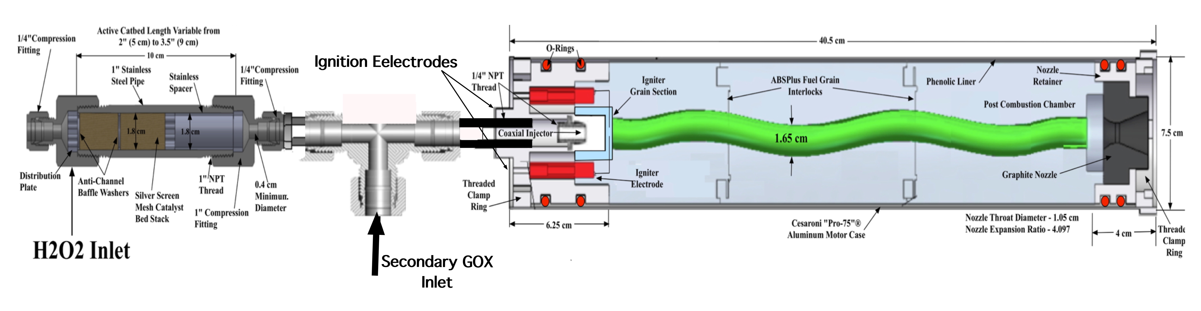
• In order to adapt the system for H2O2 as the oxidizer, a catalyst holder was installed in the oxidizer feed line upstream of the motor, with the output products funneled into the combustion chamber through the normal oxidizer flow path. The design uses a stainless steel industrial sanitary fitting and inserts directly into the flow path. The interior of the catbed holder is sufficiently long to allow for a catalyst of up to 8.25 cm (3.25 in.) long, and has an internal diameter of 2.21 cm (0.87 in.). The maximum available L/D for the catbed is correspondingly 3.75.
• The figure below shows a detail of the catbed hardware layout.
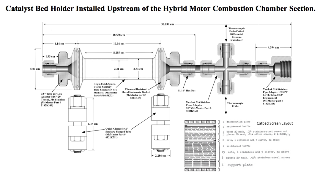
• The catalyst bed is based on an original design by Runckel, et al. In this design a series of layered silver screens, were interspersed with a mid-length anti-channel baffle, and inlet and outlet support plates. The 20 mesh screens featured 0.016 in. (0.406 mm) wire diameters and a void fraction of 0.46. The screens were treated with nitric acid for pre-activation, and compressed at 2200 psi into the catbed fitting. When fully compressed the catbed length was approximately 2 inches (5.04 cm) in length. The inlet and outlet retainer plates incorporated 5 ports that allowed flow through. The ratio of flow area to blockage for the retainer plates was approximately 20%. A 100-watt band heater was wrapped around the catbed holder, and allowed the effects of pre-heating to be investigated.
• Runckel's Original design was intended for HTP concentrations above 95%,and did not perform well in early testing with lower concentrations. The proposed research program will use the USU-patented arc-ignition system in conjunction with a catalyst bed to develop a hybrid system that allows lower concentrations of peroxide to provide sufficient heat to sustain a reaction when combined with a fuel source, as in a hybrid rocket.
• The figure below shows the secondary injection interface with the modified 75 mm motor.
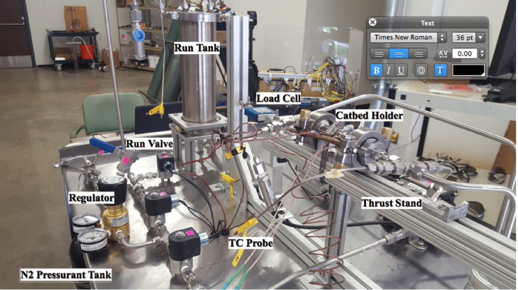
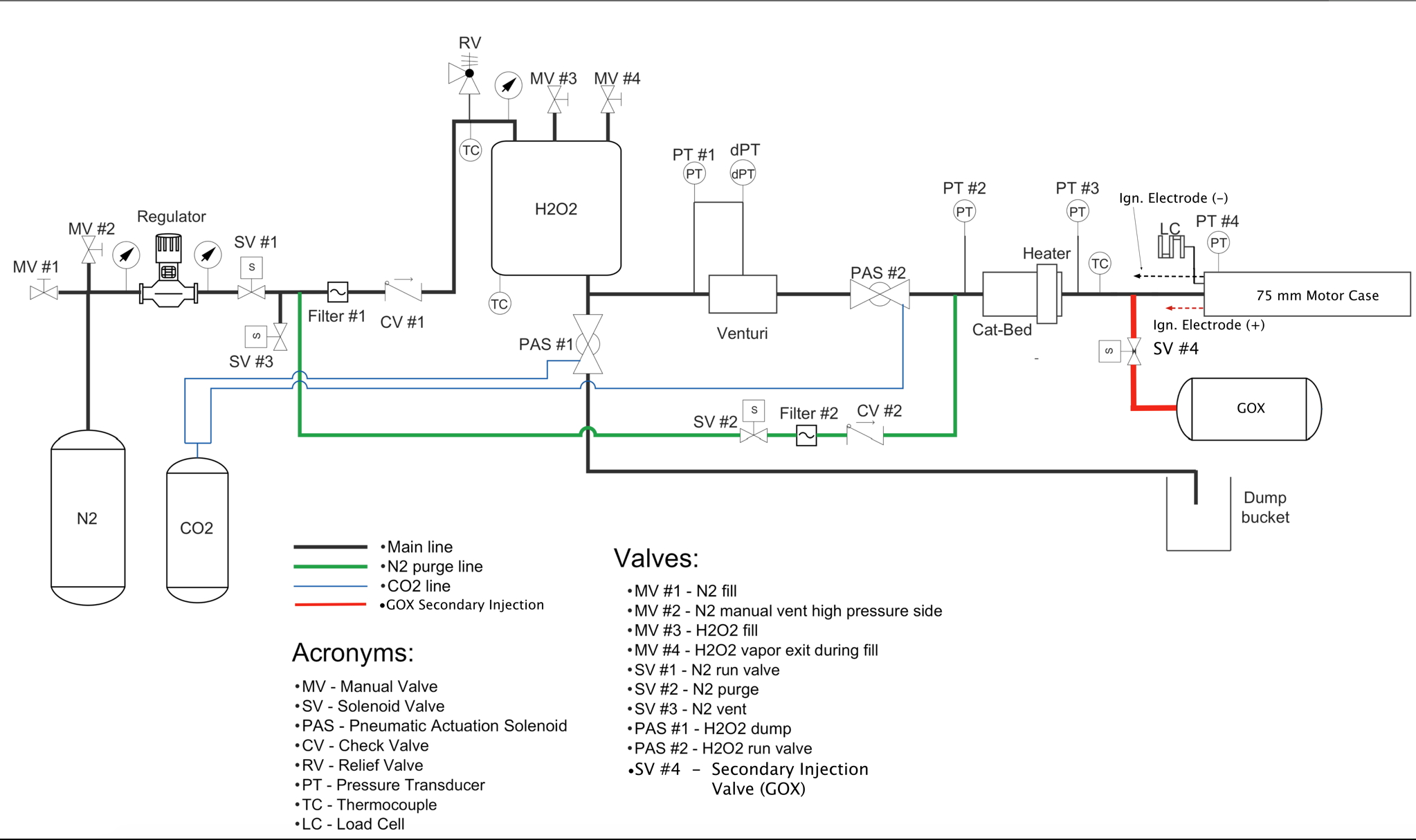
• A custom test stand, made from peroxide-compatible materials was built at USU to support ground-testing for the Phase 1 activities. The system features a 1-liter capacity run tank whose pressure is by a nitrogen gas with the top-pressure set by a manually-adjustable regulator. A calibrated venturi allows measurement of the oxidizer mass flow. The catbed inlet and outlet pressures, and the motor head-end chamber pressure are also measured. The flow temperature at the catbed outlet is sensed with a TC-probe inserted into the flow field. A separate purge system was also installed. The load structure was fabricated using commercially available aluminum "t-slot."
• The figure below shows the Piping and Instrumentation Diagram of the Test Stand
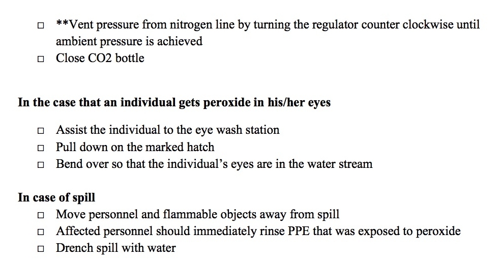
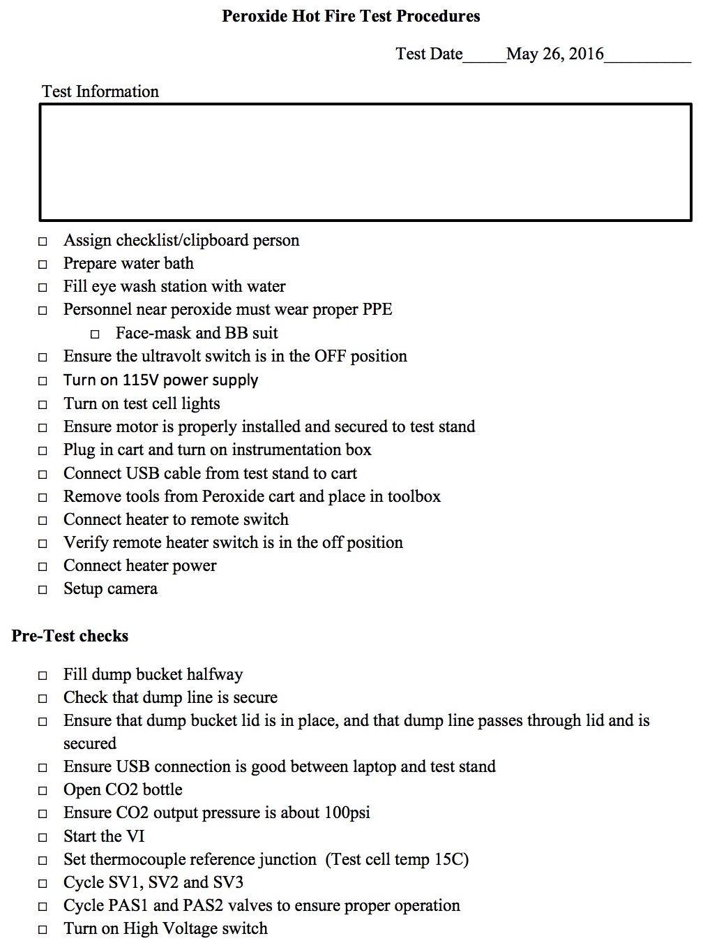
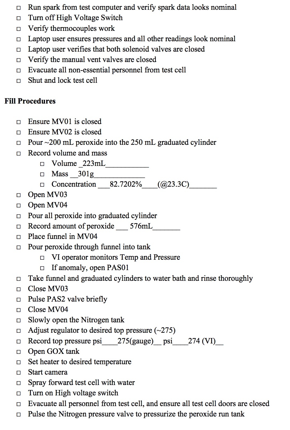
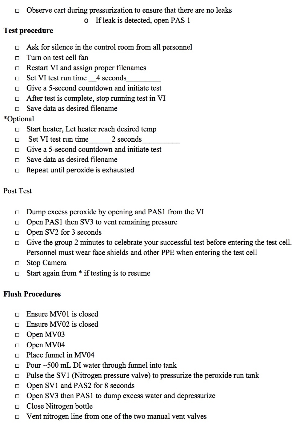
The pages below detail the initial hot fire-test procedures to be followed.
HotFire Test Procedure (pdf link)
Page 1
Page 2
Page 3
Page 4